10 Essential Components Every DIY Electronics Project Needs


1. The Power Supply: The Beating Heart of Your Circuit
No electronics project functions without a stable source of energy. Selecting the correct power supply is arguably the most critical decision. For low-voltage projects (3.3V or 5V), a regulated Linear Voltage Regulator (like the LM7805) is a staple. It provides clean, consistent DC power, crucial for sensitive components like microcontrollers. For battery-powered portables, a Li-Po battery with a Protection Circuit Module (PCM) offers high energy density, but requires a dedicated charger. Alternatively, Step-Down (Buck) Converters are superior for high-current applications because they waste less energy as heat compared to linear regulators. Always factor in the project’s peak current draw and ensure your supply can handle transient spikes. Decoupling capacitors (10µF electrolytic + 0.1µF ceramic) placed near the power input of ICs are non-negotiable to filter noise and prevent logic glitches.
2. The Microcontroller or Controller: The Project’s Brain
For programmable projects, the microcontroller unit (MCU) dictates complexity and capability. The Arduino Uno (ATmega328P) remains the gold standard for beginners due to its robust ecosystem and extensive libraries. For more advanced tasks requiring higher clock speeds or Wi-Fi/Bluetooth, the ESP32 (dual-core, Wi-Fi/BLE) offers incredible value. For simple logic without coding, use 555 Timer ICs for timing or Op-Amps (LM358) for analog signal conditioning. Key selection criteria include: GPIO pin count, ADC resolution (10-bit vs 12-bit), memory (Flash for code, SRAM for runtime), and operating voltage. Always leave at least 10% of GPIO pins and 20% of Flash memory unused for future upgrades or troubleshooting. Program your MCU using a reliable USB-to-UART converter (like the CP2102) for consistent debugging.
3. The Breadboard and Jumper Wires: The Prototyping Workhorse
Before soldering, every circuit must be proven on a solderless breadboard. These boards use spring-loaded clips to hold component leads and wires, enabling rapid iteration. The standard 830-point breadboard is ideal for medium-complexity projects, featuring power rails on both sides. Invest in pre-formed, solid-core hookup wire (22 AWG) for structural integrity and easy insertion. Dupont jumper wires (male-to-male, female-to-female) are essential for connecting modules but can be unreliable for high-frequency signals due to parasitic inductance. For analog circuits (audio, sensors), keep wires as short as possible to reduce noise. Avoid using stranded wire directly in breadboards—it crushes the spring contacts over time. Label your supply rails with colored tape (red for VCC, black for GND) to prevent accidental reverse polarity.
4. Resistors, Capacitors, and Diodes: The Fundamental Passives
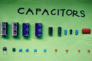
These three components form the plumbing of any circuit. Resistors control current; keep an E24 series set (10Ω to 1MΩ) handy. Use 1/4W, 5% tolerance carbon film for general use, and 1% metal film for precision voltage dividers or current sensing. For capacitors, the selection depends on application: Ceramic (50V, X7R) for high-frequency decoupling and filtering; Electrolytic (16V-25V) for bulk storage and power smoothing; Tantalum for space-constrained low-leakage circuits (but watch for voltage derating). Diodes are equally vital: a 1N4007 (1A, 1000V) for general rectification and flyback protection across inductive loads (relays, motors); a 1N4148 (100mA, 100V) for fast switching and logic-level clamping. Never omit a flyback diode across any motor or relay coil—it prevents voltage spikes that can destroy your MCU.
5. Multimeter: The Project’s Diagnostic Eye
You cannot build a reliable circuit without the ability to measure. A digital multimeter (DMM) is the single most important diagnostic tool. For DIY projects, prioritize a True RMS meter for accurate AC readings (e.g., on audio signals or transformers). Essential features include: Continuity buzzer (for tracing PCB traces and checking solder joints), Capacitance measurement (to verify capacitor values), and Diode test (to check forward voltage and short circuits). A hFE transistor tester socket is useful for identifying unknown NPN/PNP transistors. For beginners, a reliable autoranging meter like the Fluke 17B+ or a budget-friendly Aneng AN8008 is sufficient. Always measure voltage before connecting power, and check for shorts (0Ω) between VCC and GND with the power off. This habit alone prevents 90% of component failures.
6. Soldering Iron and Solder: The Permanent Bond
When a project moves from breadboard to a permanent state, soldering is the only professional method. A temperature-controlled soldering station (e.g., Hakko FX-888D or TS100) is a non-negotiable investment. Use a conical or chisel tip (1.6mm or 2.4mm) for through-hole components and a micro tip for surface-mount (SMD) work. Leaded 63/37 (tin/lead) solder with a flux core is preferred for DIY because it has a lower melting point (183°C) than lead-free (217°C), reducing heat stress and providing better wetting. Always use a brass sponge or wet sponge for tip cleaning and apply fresh solder before each joint. For lead-free (RoHS) compliance, SAC305 alloy is the standard, but it requires higher tip temperatures (350°C-370°C). Never use acidic plumbing flux; only use rosin-based flux formulated for electronics. Proper technique involves heating the component lead and pad simultaneously, not melting the solder directly with the iron.
7. Enclosure or Project Box: Physical Protection and Safety
A finished circuit is fragile. An enclosure shields against dust, mechanical stress, and accidental shorts. For prototyping, modular enclosures (like Hammond 1591 series or ABS project boxes) are ideal. They come in various sizes and can be easily drilled, cut, or 3D-printed. For RF projects, a metal enclosure provides shielding against electromagnetic interference (EMI), but requires grounding. Always include strain relief for all cables exiting the box (use grommets or cable glands). For user-facing controls, mount panel-mount potentiometers, toggle switches, and LED bezels securely with hex nuts. Ventilation slots are critical if your project includes a voltage regulator or motor driver running over 500mA. Use standoffs (nylon or brass) to mount PCBs inside the box, preventing contact with metal surfaces and providing a fixed height.
8. Wires, Cables, and Connectors: The Signal Highways
The quality of your wiring determines signal integrity and mechanical longevity. For internal wiring within a project box, use stranded hookup wire (22-26 AWG, silicone or PVC jacket) which is flexible and resists breakage. For high-current paths (batteries, motors), use 14-18 AWG silicone insulated wire to minimize voltage drop. Screw terminals (2-pin or 3-pin) are superior for removable connections (power input, sensor outputs) compared to soldering wires directly. JST connectors (PH, XH series) are standard for battery and servo connections. For data lines (I2C, UART), use shielded twisted pair cables to reduce crosstalk. Always verify polarity: mark red for positive (VCC), black for ground (GND), and use a multimeter to confirm before plugging in. Color-coding your entire build saves hours of troubleshooting.
9. Diodes, Transistors, and MOSFETs: The Switching Arsenal
Beyond simple rectifiers, you need discrete semiconductors to drive loads. For low-current switching (LED control, logic-level signals), the 2N2222 NPN transistor is a classic choice, with a current gain of 100-300. For high-power switching (motors, solenoids, LED strips), MOSFETs are superior because they are voltage-controlled (require almost no gate current). The IRLZ44N (logic-level, 55V, 47A) is a go-to for Arduino projects, as it can be fully turned on by 5V logic. Always add a 10kΩ pull-down resistor between the gate and source to prevent the MOSFET from floating when the MCU is unpowered. For AC load switching, solid-state relays (SSR) offer silent, spark-free operation, but require heat sinking. When driving inductive loads, always include a TVS diode (Transient Voltage Suppressor) or a snubber circuit (RC series) to absorb voltage spikes.
10. The Oscilloscope: Advanced Signal Visualization (But Essential for Complex Builds)
While a multimeter shows static values, an oscilloscope reveals signal dynamics. It is indispensable for debugging noise, timing issues, and communication protocols (I2C, SPI, UART). For DIY electronics, a 2-channel, 50MHz bandwidth digital storage oscilloscope (DSO) (like the Rigol DS1054Z or Hantek DSO2C10) is the sweet spot between cost and capability. Use it to: verify clock signals are clean and at correct frequency; check for analog noise on power rails (peak-to-peak ripple); measure rise/fall times of digital pulses to detect attenuation; decode serial data (many modern DSOs offer serial decoding). For high-voltage work (mains-powered circuits), always use 10x probes (with 10MΩ input impedance) and never exceed the probe’s voltage rating. A function generator paired with an oscilloscope is powerful for testing filter circuits and amplifier response.